
You dream of transforming your Campervan DIY and have never touched an electrical cable before? Or do you want to implement some changes to your Factory RV?
In this guide you will find EVERYTHING (absolutely EVERYTHING!) you need to know to create the perfect DIY electrical system for your camper.
DIY VAN CONVERSION: THE ELECTRICAL SYSTEM
Every house, to make you feel truly at home, must have electricity.
After all, in today’s world it’s really hard to do without them.
If you’re converting your own van DIY, planning to embark on a vanlife adventure for a long time, or just want to modify your camper to add a few extras, this is the guide you’re looking for!
In this article I will explain you all you need to know about the electrical system in a simple way, leaving nothing for granted.
- How much energy do you need?
- Which batteries to choose?
- How to recharge them?
- How to choose cables?
- How to make the electrical connections so that they are safe?
- Direct or alternating current?
- What protective measures should I use?
After reading this article, you will have the answer to all these questions and many more.
When I began to create the electrical system of my camper, I had never touched an electrical cable in my life: I studied, I browsed hundreds of sites and asked for advice when in doubt.
At the time, I couldn’t find any site that exhaustively explained all the steps to do and things to know, and for this it took me almost 2 months.
After my experience (and sometimes desperation! 😉 )in looking for information, I decided to write this All-in-One article on how to create the electrical system for your Campervan to make your life easier and help you to embark on the journey of crafting the right electrical system based on your own needs, even if you don’t know where to start to get your hands on.
Enjoy the reading!
Updates:
UPDATE July 2022: If you’re interested in learning about all the steps to convert a Van DIY, I’ve published the MEGA Complete Guide to Van Conversion (ps. really mammoth article 😉 ).
UPDATE November 2022: I published a New Article with additional wiring diagrams, to meet the needs of different projects 🙂
Two Videos that reassume all the Teachings of this Article
TABLE OF CONTENTS
Converting a Van: The Electrical System
1. Understanding the Electrical System (Simplified Scheme=
2. Understanding Electricity: Power (Watt), Voltage (V) and Intensity (A)
3. How much Energy do you Need? Calculate your Energy Needs with this Excel Template!
4. Batteries for RVs: Typologies, Specs and Which Ones you Should Choose
5. Connecting the Batteries (in series vs in parallel)
6. Charging your Van Batteries – Method 1: Solar Panels
7. Charging your Van Batteries – Method 2: Alternator
8. Charging your Van Batteries – Method 3: Grid Power
9. Keeping Cables Ordered: what is a Bus Bar?
10. Fuses: What are they, how to choose and how to install them?
11. How to size Wires for your Van’s Electrical System
13. How to Choose the Right Inverter for your Van
14. How to Install 110/220V AC Circuits and Plugs
15. How to Check the Charging State of your Batteries with SmartShunt and Monitor
16. Conclusion: Detailed Wiring Scheme for the Electrical System of a DIY Campervan
BONUS: Explanation of our own van’s Electrical System (ITA + subtitles)


Vuoi supportare LostOnTheRoute?
Tutte le Guide che Pubblico su questo blog sono gratuite e fruibili da chiunque perchè personalmente sono un convinto sostenitore che le informazioni debbano sempre essere un bene pubblico ed accessibile da chiunque e non un bene da acquistare. Sharing is caring 😉
Detto questo, mantenere un grande blog pieno di articoli dettagliati richiede molto tempo, molta birra (d’ispirazione ahah) e soprattutto dei costi a volte non così scontati.
Se ti può interessare aiutarmi a sostenere i costi del blog, puoi considerare di acquistare qualunque prodotto consigliato tramite i link presenti nella pagina o nella vetrina Amazon. LostOnTheRoute infatti partecipa al programma AmazonAffiliate, e per ogni prodotto acquistato tramite i link, ricevo una piccola percentuale, ovviamente a nessun extra costo per te 🙂
Buona lettura e buon lavoro! 😀
Dani

Scopri Tutti i Prodotti per Camper Fai-da-Te di qualità testata, in un unico luogo.
1. Understanding the Electrical System of a Motorhome: Simplified Diagram
Before throwing ourselves into choosing the various components of the electrical system and how to assemble them, it is vital to understand the theory of how a stand-alone system works in a motorhome.
Don’t worry, I’ll keep it short and concise.
Below, you will find a diagram made by me that explains in a general and simple way the electrical system of an RV.
As we continue in the article, we’ll look at each and every component of this scheme, get a good understanding of what is it needed for, what options are out there on the market, and which ones to choose based on your needs.
(If you already know the theory and are just looking for a practical electrical diagram to connect the wires, you can skip this introduction and go to the Detailed Diagram).

1.1 Theory: Understanding the Electrical System of your Van
The theory is simpler than it sounds:
The heart of the electrical system is the batteries.
The service batteries in a camper van can usually be recharged in four possible ways: via solar panels, alternator, external grid power, or generator.
Once charged, batteries provide power to all of your RV’s appliances and electrical services. Some run on direct current (12V) and can be connected directly to batteries, while others run on alternating current and need an inverter to convert the power to 230V (or 110V in America) to function.
The energy comes in, charges the batteries, and is consumed by you.
For now, keep this sequence and the general pattern seen above in mind. By the end of the article, not only will you be an expert on each component, but you’ll also be able to connect all the parts of your electrical system completely DIY.
2. Understanding Electricity: Power (Watt), Voltage (V) and Intensity (A)

For someone who hasn’t studied physics or never had their hands in an electrical system, these terms may seem complex. Actually, don’t worry that they’re not. In this section, I’ll explain everything about how electricity is measured (power, voltage, and intensity) and what you need to know to convert your van into a fantastic campervan.
2.1 WATTS, AMPERES, AND VOLTS: WHAT ARE THEY?
Let’s startwith the basics explained in a simple way:
AMPER
It is the unit of measurement of current intensity .
What does it mean? The ampere measures how many electrical charges pass through a wire in a given amount of time (just as the liter measures how much water passes through a pipe).
The more amps that pass through a cable, the larger the diameter of the cable will have to be (just like the more gallons of water that pass through a pipe, the wider the pipe will have to be).
VOLT
It is the unit of measurement of the difference in potential energy between two parts of a circuit.
What does it mean? At the positive pole of a circuit there is a certain potential energy, at the negative pole another. The potential difference between the two poles is what pushes electrical charges to move from one side to the other.
To make a water analogy, imagine a reservoir. The higher the tank, the faster the speed of water reaching the ground. In the same way, the higher the voltage (the difference in potential energy) between the negative and positive poles of a circuit, the faster electrical charges will pass from point A to point B.
WATT
It is the unit of measurement of current power.
What does it mean? Watts measure the instantaneous power consumed or emitted by an apparatus/appliance. It basically measures how many electrical charges an apparatus uses to operate. As we have seen, the electric charges that pass through a wire we measure in Ampere, while the speed with which they move we measure in Volt.
To measure Watts, the number of electrical charges emitted or consumed by an apparatus, we use the formula:
Watt = Volt x Amper (W = V x A)
Multiplying therefore the operating voltage of an apparatus (Volt) by the intensity of the current that is consumed or emitted (Amper), we obtain its Wattage (Power consumption).
2.2. Electrical System in a Motorhome: What do I need this knowledge for?
Watts, Amper, Volts…interesting! But why do I need to know these things for converting my van?
Well, memorizing and internalizing the sacredformula W=V*A is the basis for making the decisions you need to create a safe and secure electrical system tailored to your needs. Among other things, with this formula you will be able to:
- Calculate your daily energy needs
- Calculate the power of solar panels best suited to your needs
- Understand which and how many batteries you should buy
- Calculate what fuses to install to protect your electrical system from failures/overloads
- Calculate which inverter you need and how much it consumes
- Figure out how many hours per day you can use the various devices on your RV without over-draining the batteries
- Orient yourself on the diameter of the cables you will be installing
- And much, much more!
We’ll learn about all of these things together, one by one, in the various chapters of this article (with ample examples to really understand everything!). For now, all you need to remember is the sacred formula of electricity: W=V*A. 😉
3. How much energy do you need?
Calculate your Energy Need

The first thing you need to do to create the perfect electrical system for your RV and your needs is one: PLANNING!
There is no one-size-fits-all electrical system. For some people, 230V plugs are essential (imagine charging a computer!), for others a USB to charge their phone may be more than enough… If you plan to install an induction stove, you will need a much larger battery bank than those who plan to cook with gas… etc. etc. etc.
What batteries do you need? What solar panels do you need? What inverter do you need? What appliances will you be able to use?
The answer to all these questions necessarily starts with calculating YOUR energy needs. In the next paragraph, I will help you do exactly that.
3.1 Download the excel template to calculate your Energy Needs
How much energy do you need in your DIY Campervan?
Download the Excel Template to get started: it’s a file I prepared to help you automatically calculate the energy needs of your future converted van. You enter the data, and he will magically give you the answers you are looking for 😉
Once you have downloaded the template, open it. It will appear like this:

A little empty right now, but you’ll fill it up soon 😉
The green cells are the ones you will have to fill in, while the others are calculated automatically (don’t touch them!).
3.2 Fill in the Excel Template with your numbers
Now back to us, to calculate your energy needs (how much energy you will use each day), you must assume which appliances and equipment you will use on a daily basis and for how long (hours or minutes).
What electrical equipment do you plan to put in your RV? I’ll leave you with a few ideas here:
- Led Spotlights
- Led Strips
- Fridge
- Water Pump
- Heating
- Ceiling Fan
- Air Extractor
- Induction hob
- Hair dryer
- PC/Telephone Chargers
- Inverter
- TV
- …
Write in the column “Appliances” everything you plan to install or connect to the electrical system of your motorhome and in the column “Quantity” the number of each piece of equipment (example: fridge: 1, led spotlights: 8, etc).
How many hours per day could you get to use each one? Example:
- Led spotlights (5 hours)
- Fridge (24 hours)
- Water Pump(15min –> 0.25hrs)
- TV (90 minutes –> 1.5 hours)
- Induction hob (30 min –> 0.5 hours)
- …
Once you have estimated your maximum daily usage of each device, enter this value in the “Daily Hours” column, making sure to translate minutes into hours (15min= 0.25 hours, 30min= 0.5 hours etc.).
Direct Current 12V or Alternating Current 230V?
Now that you’ve thought about what you’d like to install on your camper van and how long you’d like to use your electrical equipment for, the hard part is done. Now you only need to fill in the remaining columns mechanically.
In the “Voltage” column, enter the Volts at which the different devices/appliances operate. In this column you will normally have only two values: 12V for direct current devices (e.g. spotlights, water pump, fan etc.) and 230V (110V in America) for alternating current devices (e.g. TV, PC charger, hair dryer etc.).
If you are unsure about the voltage of an appliance, look it up in the owner’s manual or on the nameplate on the back or charger of the appliance you plan to install.
Insert the Wattage of the Various Devices
Once you have entered the voltage (V), enter in the “Wattage” column the maximum watts consumed by each device/appliance.
To find out what the maximum wattage of a device is, again consult the instruction manual.
3.3 Observe the Magic, and Discover your Daily Needs

When you have finished entering all the data, the excel template will automatically calculate your maximum daily energetic consumption, measured in Watts/hour (Wh = Watts x hours). (In the image above is an example of my daily requirement).
This information will help you figure out which batteries and inverters you might need to install to meet your needs.
Using the sacred formula W=V*A we can easily divide the total Watts/hour by the battery voltage (12V) and find out what battery bank (minimum) you will need to run all your equipment on an average day.
The amount of energy that can be stored by batteries is measured in Amper-hours (Ah).
Still looking at the Excel sheet, you can see how many of the total Watts will be consumed by your low-voltage 12V devices, and your high-voltage 230V (or 110V) equipment.
The sum of the maximum Wattage of all the 230V equipment is your maximum instantaneous AC demand: to meet it (i.e. to run all these AC equipment at the same time), you will need an Inverter that can release, at least, that amount of power. As we will see in chapter 13 How to Choose an Inverter for Your Motorhome/Van, this number is not necessarily the power of the inverter you need, but only a number to orient yourself on which you will then have to think a little bit more.
(Normally, a 15% is added to the sum of the Watts consumed by AC power to account for the power loss that the inverter produces during conversion, we will talk more about this later).
Now that you’ve calculated your daily energy needs and thought about what you’d like to install in your converted van, it’s time to start building your electrical system: first by getting the right components, and then connecting them in the right way.
4. Batteries for Camper: Types, Features and Which to Choose
Let’s start with the heart of your electrical system: the batteries!
4.1 “Starting batteries” vs “Service batteries”
Batteries are your power tank and having a proper battery bank can mean the difference between a comfortable home on wheels and having to eat dinner in the dark.
All vehicles, including converted vans and motorhomes, already have a starting battery (also called “ignition battery”) which is the battery that starts the vehicle, powers your vehicle’s lights and is constantly recharged by the alternator whenever the vehicle is in motion.
The starting battery, is what starts your vehicle. It’s installed for that and that alone. Without it, you’re stuck. For this reason, it should never be used to feed other devices.
So, what kind of batteries were we talking about until now?
To power all of your equipment (DC and AC), what you need is Service Batteries: deep cycle batteries (deep cycle = that release constant energy) that you will install exclusively to power the comforts of your house on wheels.
These are the ones we’ll look at in the next section.
4.2 Types of service batteries
Technology is evolving faster every day, and with it the technology of batteries, their convenience and their prices.
Right now, if you are planning the electrical system for your converted van, there are essentially four kinds of battery alternatives on the market.
In this paragraph I’ll leave you with the Pros and Cons of each type of battery and once illustrated I’ll reveal which ones I chose to install on my VW Crafter and why.
Lead Acid Batteries (FLA)

The oldest technology, relies on a chemical reaction between lead and liquid acid to store energy.
PRO
- Low Initial Cost
- Various sizes are available
- Proven Technology
- With proper maintenance, it can last up to 5-8 years
CONTRO
- La Tecnologia più Arretrata
- Mediamente Ingombrante
- Se si scarica sotto il 50% si rovina e si riduce la vita utile
- Se sovraccaricate o urtate, possono rilasciare gas potenzialmente pericolosi (acido, idrogeno)
- Nel peggiore dei casi, possono persino esplodere
- Richiedono Manutenzione Regolare, anche quando non in uso
- Possono emettere fumi acidi/tossici, non consigliate per la zona abitativa
PERSONAL OPINION
The relatively low price doesn’t balance out the various cons. Lead-acid batteries are a backward technology and in the recreational vehicle field, dominated by other options.
Not recommended.
GEL Batteries

Similar to FLA batteries, but with gel instead of liquid acid. Higher performance and less labor intensive to maintain.
PRO
- Do not release hazardous gases
- They are sealed and there is no risk of leaking liquids
- Can also be installed horizontally
- Withstand extreme climates well
- Maintenance free
- Can be left unused for long periods (up to 6 months)
AGAINST
- Battery can be damaged if it is emptied more than 80%.
- More expensive than FLA or AGM
- Recharge Slowly
- Can be damaged if overloaded
- Average longevity of 2-4 years
PERSONAL OPINION
Gel batteries are a good quality/price option. By paying attention to the charging process, they are a good low cost, maintenance free option.
AGM Deep Cycle Batteries

AGM batteries are the standard for most motorhomes and RVs and are still the most widely used batteries today.
PRO
- Maintenance free
- 20% smaller than GEL batteries
- Can be left unused for long periods (up to 6 months)
- Can be installed horizontally
- Sealed: no risk of gas leakage
- Vibration resistant
- Longevity of 4-7 years
AGAINST
- Bulkier and heavier than LifePO4
- If it discharges below 80% it will be ruined and reduce the useful life (normally you should use them up to 50% only)
- Higher cost than FLA and GEL
PERSONAL OPINION
AGM batteries are high-performance, safe and affordable. If you don’t have space/weight issues and don’t want to spend too much, AGMs are the perfect choice for you.
Lithium-Phosphate LifePO4 Batteries

Lithium-ion batteries are the most advanced battery technology today, and despite being the most expensive, prices are starting to come down.
PRO
- The most compact and lightweight batteries
- Can be discharged up to 90% (deep cycle)
- For this reason, you need less Ah
- Maintenance free
- Can be left uncharged for long periods (up to 6 months)
- Longevity: Long Life (8-20 years)
AGAINST
- Very high initial investment
- Do not charge with temperature below 0°C
- Often require chargers/isolators/software specific for LifePO4 batteries
PERSONAL OPINION
LifePO4 batteries are the latest generation: lightweight, compact and up to 90% deep cycle. They cost about twice as much as AGMs and GELs, but they also have a longer longevity.
4.2 Choosing the Right Batteries for You
Choosing the right battery for you, depends entirely on your needs, where you want to travel and for how long. Below I leave you with a summary of previous information to help you choose:
- Leave FLA batteries alone, they are not performing and can be dangerous.
- The lightest and most compact batteries are LifePO4 (less than half of an AGM/GEL)
- The best batteries for extreme climates are GEL batteries
- The most convenient batteries quality/price are the AGMs
- The most expensive batteries are LifePO4
- The longest lasting batteries (up to 20 years) are LifePO4
In addition, it is important to note that It is strongly discouraged to completely drain the batteries:they will be damaged and their durability and longevity will be compromised. Therefore, the Ah (Amper/hour) that can be used of each battery are not the nominal ones but rather:
- For GEL batteries it is recommended not to use more than 50-60%.
- For AGM batteries it is recommended not to use more than 50-60%.
- For LifePO4 batteries, it is recommended not to use more than 90%.
What does this mean? As an example, the usable Ah (Amper/hour) from a 100ah AGM battery will be 50ah, while from a 100ah LifePO4 will be 90ah.
Depending on the manufacturer, this number may change slightly, but now you have an idea of how many Ah (Amper-hours) of a given battery type you may need to meet your energy needs.
In the next paragraph, I’ll explain what data to look at when deciding which battery to buy.
4.3 What data to observe when purchasing a battery
When buying a battery, we need to keep an eye on some data to see if the battery actually meets our needs. Below, find the most important points to focus on:
Example data sheet of my batteries (LifePO4):

- 1 – Nominal Voltage: The voltage of all service batteries for motorhomes and vans is 12V. This is the voltage that the vast majority of RV equipment runs on (fan, water pump, lights etc.) and is the voltage you need for your batteries. Make sure this parameter is around (slightly above) 12V.
- 2 – Nominal Capacity: The capacity in Ah (Amper/Hour) of the battery. Remember that this is only a nominal figure and, depending on the type of battery you choose, you will be able to use more or less of it (AGM/GEL 50%, Lithium 90%).
- 3 – Life Cycles: These are the life cycles that a battery has. In the case of my battery, it has 2000 charge cycles, charged and discharged at 0.2C which is in 5 hours. (1C is equivalent to 1 hour, the more “C” is high, the better the battery can withstand rapid charge and discharge cycles)
- 4 – Charging Modes: here you can see the charging voltages, useful when you have to buy “battery chargers” for solar or alternator (we’ll talk later)
- 5 – Maximum Charge Current: this is the maximum current with which you can charge the battery. In the case of my battery it is 50Amp. This means that the 100ah battery could potentially charge in 2 hours.
- 6 – Maximum Continuous Current: How much current can be released from the battery continuously. In my case 80A was not enough for my electrical needs (having planned an induction hob), however by combining 3 batteries I reached 240A, at this point sufficient.
- 7 – Operating Conditions: Charging, discharging, storage temperature and resistance to water and dust.
- 8 – 9 – Dimensions and Weight: If you have limited space in your project (as I did) it will be very important to check the dimensions of the battery before buying it to be sure it will fit in your vehicle.
4.4 What I installed on my VW Crafter: LifePO4 batteries
Nel mio progetto di camperizzazione, mi ero messo in testa di avere un piano a induzione per cucinare.
Sinceramente non me la sentivo di dover lavorare con il gas, ed in più, farmi omologare il sistema gas in Germania prima di fare il collaudo (se vuoi saperne di più su come ho omologato il mio furgone leggi Come Omologare un Furgone in Italia – La Guida Completa ).
Per questo, avevo bisogno di stoccare molta energia elettrica (circa 250-300ah).
Sei batterie AGM da 100ah (6 batterie x100ah potenza x50% scarica max. consigliata = 300ah) mi avrebbero occupato troppo spazio che mi serviva per altre cose (lo spazio in un van è poco e molto prezioso!) e che non ero disposto a compromettere.
Al contrario le batterie al litio LifePO4 che ho trovato erano compatte e tre erano sufficienti per coprire il mio fabbisogno (3 batterie x 100ah x 90% scarica max. consigliata =270 ah). Aggiungendo la maggiore longevità delle LifePO4 rispetto alle AGM, (pianifico di viaggiare full-time per molto tempo) decisi di fare l’investimento.
I prezzi che vedevo in giro mi lasciavano molto perplesso. Addirittura 1000 Euro a batteria, fuori di testa!
Dopo tanto cercare, decisi di fidarmi del sito BatterieLitioItalia (ex. Camperbattery), un sito italiano che offriva batterie LifePO4 a prezzi di fabbrica veramente stracciati rispetto alla concorrenza. Ordinai 3 batterie LifePO4 di 100ah l’una a 425 Euro l’una, e incrociai le dita. Il sito diceva che i tempi di invio erano intorno ai 30/45 giorni, io essendo all’inizio della mia camperizzazione, non avevo fretta.
Dopo 25 giorni, ho ricevuto le mie batterie ben imballate e wow, funzionano benissimo!
Ora mi sento di poter super-raccomandare il sito BatterioLitioItalia del signor Omar Dalla Porta, sono molto affidabili e sinceri con il cliente, è stato facilissimo contattarli per telefono (quando chiesi come procedeva l’ordine) e in più offrono una garanzia fino a 5 anni sulle batterie.
Qui le foto delle mie batterie prima di essere montate:


In Conclusion: Choose the Batteries that best suit YOUR project!
I chose LifePO4 batteries for saving space and for their longevity and searched the internet for days to find them at a reasonable price (still high!).
To conclude the choice of your battery, take a good look at the energy needs that you have just calculated. Then set yourself a budget of how much you want to spend. Think about the use you plan for your batteries, examine how much space in your vehicle you’re willing to set aside for the battery bank, and see what’s on the market. So make your informed choice 🙂
There is no such thing as a one-size-fits-all battery, each convertion project is unique😉
Once you have chosen and ordered your batteries, you can continue with the next paragraphs, in which I will explain how to connect them and the various charging alternatives.
5. How to connect Batteries (in series or parallel)
The heart of your van’s electrical system, especially if you plan an off-grid system (ie independent from the grid), are the batteries.
Therefore, the first step in installing your electrical system is to connect the battery bank .
If you only have one battery, the problem does not arise: there is a positive and a negative pole, and everything else will be connected to these two poles.
If, however, one battery is not enough to cover your energy needs (as in my case) I will now explain how to connect more than one in the correct way.
5.1 How to connect several batteries in parallel (not in series!)
The easiest way to power 12V equipment (most of the equipment that is normally installed in a campervan/converted van) is obviously to have batteries that run on 12V.
If we want to combine several 12V batteries, increasing the Ah (Amper/hour) available to us but keeping the voltage constant at 12V, we must connect our batteries in parallel .
In my case, I decided to combine 3 100Ah batteries to get the 300Ah I needed.
Below I leave a diagram of how I connected my batteries. (If you’re looking for a practical guide on how to calculate the right cable cross section for your batteries or how to connect lugs to batteries, we’ll talk about that later in the article).
ATTENTION: when connecting several batteries, make sure they are all identical (same size and manufacturer). This will prevent energy imbalances and make your batteries last longer.
STEP 1. Connecting Batteries in Parallel

To connect multiple batteries in parallel, connect the positive poles to each other and the negative poles to each other. Follow my diagram to get the greatest balance of charge/discharge between batteries (so as to maximize their longevity).
Once the batteries are connected in parallel, they will virtually become one big battery, where the Ah will be added while the voltage will remain the same (12V).
In the next few chapters, we’ll look at the various ways to recharge our battery bank.
6. Recharge the Batteries of your Campervan Method 1: Solar Panels
The first method of recharging the batteries of your camper/converted van is solar panels.
Nowadays, solar panel technology has evolved a lot and it’s totally possible to recharge your RV’s service batteries not only in the summer, but also in the winter!
The roof of your vehicle is the perfect space to place solar panels. For a guide on solar panels on the market and how to choose the perfect panels for you, I refer you to the Complete Guide to Choosing and Installing Solar Panels for your Motorhome.
Instead, in this article, I will simply show you the diagram on how to connect solar panels to your batteries.
On my van, I installed 600Watts of solar panels (3 panels of 200Watts each, with a voltage of 12V). Having planned my entire system at 12V, I connected my panels in parallel and this is the example I will show you in the diagram.
STEP 2. Connecting Solar Panels in Parallel

Once you’ve connected your solar panels to each other (if you plan to install more than one), it’s time to connect your panels to the battery.
Unfortunately, solar energy is not constant, but varies according to a thousand variables: time of day, season, weather, latitude, etc. For this reason, you cannot directly connect solar panels to the battery (power surges would ruin the battery instantly).
So how can you harness the solar energy your panels produce to recharge your RV’s batteries?
To make the solar energy constant and usable we come to the aid of the charge controllers.
6.1 What is a charge controller and which one to choose for your project
A charge controller is a device specifically created to make solar energy “homogeneous” and usable.
A charge controller, in fact, limits the rate at which electric current is administered to the service batteries . It prevents overcharging (if the batteries are charged, it stops sending power) and can protect against overvoltage, which can reduce battery performance, ruin your battery life, and can be a dangerous safety hazard.
Which Charge Controllers are on the market and which to choose?
Beyond the various brands, charge controllers are divided into two types: PWM and MPPT.
In this article I will not go into specific details of how both types of charge controllers work (if you want to learn more I recommend this article), but I will explain only the main difference that you need to know to choose which controller to mount in your electrical system.
An MPPT (Maximum Power Point Tracking) charge controller can channel the maximum power produced by the solar panels to the batteries at any given time. A PWM (pulse width modulation) charge controller, on the other hand, is not.
For example, if a photovoltaic panel is working at 18V and the battery is working at 12V, the MPPT charge controller can convert the 6V surplus into extra energy (extra amps for your battery). Conversely, with a PWM controller, the surplus is lost.
In general, an MPPT charge controller converts between 15-30% more energy than a PWM. The advantage of the PWM charge controller though, is that it generally costs one-tenth the cost of an MPPT.
Regardless of the type of charge controller you choose (PWM or MPPT); for it to be right for you, make sure before purchasing that the device is powerful enough to process all the energy (amps) coming from your solar panels.
Installing an undersized charge controller will not allow you to fully harvest the power of your solar panels.
Below, I leave you with two of the best charge controller models (PMW and MPPT) with tips on when to choose one or the other:
PWM charge controller

Best Budget Option
- It has an efficiency around 75%
- Reduced cost compared to MPPT
- Suggested for small projects
- Suggested for projects where efficiency is not crucial
- The most popular technology
- Solid and Durable Product
Generic MPPT Charge Controller

Best Quality/Price Option
- Efficiency reaches 99%
- Median price and good quality
- Works for FLA, GEL, AGM batteries
- Not suitable for LifePO4 batteries
- Suggested for larger projects
Victron MPPT Charge Controller

Best Premium Option
- Efficiency reaches 99%
- High initial investment cost
- Can also connect higher voltage solar panels to the battery
- Suggested for larger/serious projects
- Allows Charge Monitoring via Bluetooth
6.2 My Choice: Victron MPPT Charge Controller
After a long and careful research, I decided to invest in a Victron Smartsolar MPPT Charge Controller for my VW Crafter.
My reasons were as follows:
- for the induction hob, I needed all the available watts
- optimize energy production even in winter
- I love the ability to keep an eye on my energy production via Bluetooth on my smartphone
- an MPPT regulator optimizes the charge and longevity of my LifePO4 lithium batteries
- I leave the door open to install solar panels of different voltage in the future
- I plan to travel a long time so I was looking for something that would last a long time
- Victron is one of the best known and renowned brands in the industry, a name a guarantee!
Having a certain project in mind, I found this charge controller to be the closest to my idea of conversion. Obviously, in making your choice, you’ll need to think about your design and how you intend to use your vehicle in the future.
Having 600Watt polycrystalline solar panels operating at 12V (with 22V peaks), I opted for the 150-45 version where 150 are the maximum accepted voltage of the solar panels, and 45 is the maximum amperes that can be passed to the batteries.
From the manufacturer’s manual, the maximum current I can expect to produce is 11.5 Amper per panel, which multiplied by 3 panels, gives 34.5Amp. I chose a charge controller that can handle up to 45Amp input to give me some margin, should I decide to add an additional panel in the future or change the current panels to better performing ones.
6.3 Connecting the solar panels to the service batteries via the charge controller – diagram
Once you’ve chosen the charge controller that best suits your needs, it’s time to connect it to the battery bank.
Below, I leave you the diagram on how to connect the cables:
STEP 3. Connect Panels and Charge Regulator to batteries.

The connection is very simple: each charge controller has four inputs, two for the cables coming from the solar panels (+ and -) and two for the cables going to the service battery bank (+ and -).
To properly connect your PV system, the only thing you need to do is simply make sure to connect each cable as indicated on your charge controller(battery +, battery -, PV +, PV –).
Once everything is plugged in, the magic of solar power will begin to charge your batteries 🙂
NOTE: Later in this article, I will teach you how to calculate the section of the various cables you need to connect all parts of your system.
NOTE 2: Later in this article, I’ll explain what fuses are, how they protect your electrical circuits, how to calculate the size you need, and how to put them in all your circuits (including the one you see now in the diagram for solar power).
7. Recharge the Batteries of your Campervan Method 2: the Alternator

The alternator is a rotating electrical machine found in every vehicle that converts the mechanical energy generated by the engine into electrical energy.
When the engine turns, the alternator produces energy. While you’re driving, you’re generating electricity.
Normally this energy is used to charge and maintain the ignition battery. This way, whenever you try to start the car, it will turn on, the headlights will turn on, the warning lights will turn on etc….
The alternator is the device that constantly recharges your ignition battery by harnessing the mechanical energy created by the engine.
So, why not use the alternator to charge your service batteries TOO?
The alternator recharges your ignition battery, so you could connect your service batteries to the ignition battery to transfer electricity from one another, right? Not really.
If you directly connected the two batteries, you would risk emptying the ignition battery every time you use your devices (induction, lights, fridge, hairdryer, etc.); after all, the ignition battery generally has a much lower capacity than a service battery bank.
To recharge the service batteries, we then need a way to connect them to the ignition battery only when the engine is running and the alternator is producing a “surplus” of power, and disconnect them when the vehicle is off.
Depending on the type of batteries mounted on our vehicle, this job can be done by a battery isolator (manual or intelligent) or a B2B charger.
Below, I’ll briefly explain how teach of them works, so that you can judge which one might be right for you:
Manual Battery Isolator

Best Budget Option
A manual isolator between two batteries is a switch that requires special attention. In fact, it will be your duty to connect the batteries while driving, and disconnect them once the vehicle is turned off.
- Minimum Cost
- Very simple mechanism
- Does the work for which it is made for
- Works for FLA, GEL and AGMBatteries
- You must remember to activate and deactivate it manually
Intelligent Battery Isolator

Best Quality/Price Option
An intelligent isolator needs no manual intervention. It autonomously senses when the vehicle is in motion and connects the batteries together.
- Cost Content
- Very simple mechanism
- Does the work for which it is responsible
- Works for FLA, GEL and AGBatteries
- Install it and forget about it
B2B Battery Charger (Victron Orion)

Best Premium Option
A B2B Battery Charger boosts a complex algorithm that allows LifePO4 lithium batteries to be charged by the alternator.
- High Cost
- Also charges LifePO4 batteries
- Complex Software
- Can be monitored via Bluetooth
- Install it and forget about it
7.2 DIAGRAM FOR CONNECTING A B2B CHARGER OR ISOLATOR
Regardless of which B2B isolator/charger you choose, the electrical connection is identical and very simple.
In my case, having chosen LifePO4 lithium batteries, I had to buy a Victron Orion 12-12 30, and this device is the one I will use in the wiring diagram as an example. The isolators are connected in the exact same way.
STEP 4. Connect a B2B Isolator/Charger between the two Batteries

The alternator is already connected to your vehicle’s ignition battery (in fact, it is always charged because it is charged every time you start the engine). Therefore, we don’t need to touch it.
To install our B2B isolator/charger, all we need to do is insert it between our ignition battery and our service batteries: red (+) and black (-) cable from the battery to the isolator, and then red (+) and black (-) cable to the service batteries. Simple and intuitive.
NOTE: The ignition battery is normally at the front of your vehicle, while the service batteries, depending on your design, may be at the back. I recommend you think how you’re going to pull the cables from one end of your vehicle to the other in the planning stage (maybe placing a tube already). Study your van/campervan layout well to figure out the best way to run wires between the two batteries.
Once you install your B2B isolator or charger, you’ll be able to charge your batteries just by driving. Charging batteries with the energy created by the alternator is an independent charging method that comes in very handy in the absence of sunshine or charging stations, perfect for boondocking or wild camping.
In my case, having installed a Victron Orion, I can monitor my charging directly via Bluetooth with the Victron Connect App. Below I’ll leave you two screenshots of the app so you can see what happens when my vehicle’s engine is on or off.
With Engine Off (Battery Disconnected)

With Engine Running (Batteries Charging)

8. Recharge the Batteries of your Campervan Method 3: Charging from the Grid
In addition to solar panels and the alternator, there is a third method of recharging your vehicle’s service batteries, and it’s the one normally used by factory motorhomes: the electrical outlet (grid power – shore power).
The grid power option consists in simply connecting to the 220V/110V grid through a home, garage, or camping socket, and drawing from the grid the energy to recharge the service batteries (or in the case of factory campers, to power their equipment directly).

8.1 Attention: recharge batteries or supply 230v directly to the van devices/appliances?
The vast majority of factory RVs (those vehicles that are already born RVs), are not designed to spend many days away from the power grid. If they have solar panels installed on the roof (most don’t), they are normally small to medium-sized, and are only used to power 12V DC circuits.
Most RVs do not have an inverter connected to the batteries!
How then do the circuits of “factory” RVs work?
Simply, most campers have two circuits: one working at 12V DC (normally recharges through the alternator) which powers the lights and low-consumption devices; and one working at 230V AC (or 110V in America) that can be used only when the campervan/motorhome is connected to the grid (as an example, when it is parked in a camping).
The high voltage circuit (230V AC) is totally independent from the service batteries: connected to the mains, it works; disconnected from the mains, it doesn’t work. Basically, in order to use your AC equipment (e.g. computer, TV, kettle, hair dryer, etc.) you must be stationary and connected to a wall outlet.
For D-I-Y van conversion projects, I know, the goal is usually not that, but instead to be energy independent for as long as possible.
For this reason, in this section of the article, I don’t want to explain how to create an AC circuit (which we’ll talk about later), but I simply want to explain how to charge the service batteries of your camper van using an external outlet.
8.2 Recharging the Batteries with Shore Power: the Battery Charger
Mains power is supplied by the high voltage electrical grid (in Europe 220-240V AC, in America 110-120AC).
Our vehicles’ batteries are normally 12V DC (or at max 24V). The batteries, therefore, work at a much lower voltage and with direct current, instead of alternating current.
For this reason, we cannot directly connect batteries to an AC outlet: they would instantly overheat to the point of exploding and catching fire.
So how can we recharge the batteries of our vehicle without creating dangerous situations?
To recharge our batteries with electricity from the grid, what we need is a battery charger.
Have you ever wondered why you need an adapter to charge your phone and can’t plug it directly into an electrical outlet? If you pick up your cell phone charger, you can read on it (in small print), the entry current’s voltage (220-230V) and the output current’s voltage (12-14V). That charger, adapts the current coming from the electrical outlet to the one required by your phone to charge.
To charge the batteries of a vehicle, the process is exactly the same as to charge the batteries of a cell phone: you have to adapt the current of the electrical outlet to the current required by your batteries.
This can be done through battery chargers, obviously slightly larger than the one you use for your cell phone.
Below I leave you with two good charger options that you can review and evaluate based on your needs. In the following section I will explain with a diagram how to connect the charger to your batteries.
Smart Charger

Best Budget Option
A Mobile Charger, small but powerful. Suitable for those who plan to occasionally connect to the grid to charge FLA, GEL or AGM batteries
- Cost Content
- 30Amp Charging Power
- FLA, GEL and AGMbattery chargers
- Mobile
- Occasional or Emergency Solution
Victron Phoenix Smart Charger

Best Premium Option
A Charger with Complex Algorithms for a permanently installed solution. Charges all types of batteries.
- Higher initial investment
- Charge also LifePO4 batteries
- Overcharging Protection
- Can be monitored via Bluetooth
- Install it and forget about it
- Available in various sizes (and prices)
Ogni adattatore viene in varie taglie. Più è grande, più energia può convertire e più caricherà velocemente le tue batterie. Ovviamente anche i prezzi crescono rapidamente con la potenza del caricatore.
Per scegliere quello giusto per te, ti consiglio di leggere sulle tue batterie la massima carica d’entrata (non avrebbe senso inviare alle batterie più energia di quella che riescono ad assimilare) e partire da li per vedere quale caricatore può essere il più efficiente per il tuo progetto e le tue tasche.
Nel mio caso, avendo batterie al litio LifePO4 e tutto il sistema già interconnesso e gestito dalla app VictronConnect, ho scelto di installare un Victron Phoenix Smart 12-30|1+1, dove 12 è il voltaggio di output, e 30A la corrente massima di ricarica.
UPDATE 2022: Victron ha rilasciato un nuovo caricabatterie per camper (Victron Blue Smart Charger) con le stesse funzioni e potenza del Victron Phoenix Smart, ma meno ingombrante e più economico. Se stavi pensando anche tu come me ad un caricabatterie Victron, ti posso consigliare di andare con il secondo 😉
8.3 come connettere il carica-batterie: schema
Per far arrivare la corrente elettrica da una presa esterna fino all’interno del vostro furgone / van, sicuramente vi servirà una prolunga ed installare una spina di alimentazione adeguata (specifica per i camper) per collegare la prolunga in sicurezza.
Di seguito, ti lascio i due prodotti che uso/ho installato io (nel caso volessi copiare la mia installazione) ed un paio di immagini della mia entrata.

3-Pole Extension Cable (20meters)
Useful for connecting to electrical plugs in campsites/service areas

CEE Power Plug for Van / Campers
To be mounted on one side of your vehicle for easy recharging.
If you’re interested in seeing how I mounted my power plug, I talk about that in another article: Entry Holes for the Amenities in your Converted CamperVan.

The 230V alternating current from the column arrives through cables made of 3 copper wires: one blue, one brown and one green/yellow. These wires (which we’ll look at in more detail later in the “cables” section) are:
- Brown: Phase Conductor. This is the cable that should be handled with the most care, through which the 230V electricity reaches the device to be powered.
- Blue: Neutral Conductor. It is crossed by the “return” current, i.e. the current that has already passed through the affected apparatus and is ready to return to the circuit.
- Yellow-Green: Protection Conductor. Discharges surplus and overcharges of electricity (and saves your life if anything goes wrong!) In the case of mobile vehicles, it is attached to the body of the vehicle.
In case you have chosen the non-permanent solution, once you have connected your charger to the mains all you need to do is simply take the clamps and connect them to your batteries until they are charged.
If you’ve chosen a permanent solution (like me), you’ll have to do a bit of work, stripping and crimping the wires (as I’ll explain in the appropriate section) to connect them to the charger in the correct way.
Below is a diagram of how to install your charger so that you can charge your batteries via the mains/grid connection.
STEP 5. Connecting a charger to recharge from the Electrical Grid

9. Keeping Cables Orderly: What is a Bus Bar?
As you probably noticed in the last diagram (STEP 5), if you chose to install more than one charging system in your converted van, you probably already have many positive (+) and negative (-) wires all flowing to the positive (+) and negative (-) terminals of your battery bank. And that’s still not all of them!
Having too many cables converging in a single pole is neither safe nor advisable: it increases the risk of accidental contacts and makes maintenance operations much more complicated. If you’re planning a permanent van conversion project, I recommend (as I did) using bus bar boxes.
9.1 What are bus bar boxes and how do they work?

Bus Bar 300A
To keep battery charging and discharging cables neat and safe.
A Bus Bar is essentially a protective box containing a brass/nickel bar with several pegs (in my case 4).
Each Bus Bar has a maximum amperage and voltage, which changes depending on its size.
Each rung of the bus bar is connected to all the others and shares their electrical energy.
Simply put, a bus bar is a more spacious “coupler” where you can run several cables together without having to attach them all to the same bolt on top of each other.
In this way, the cables remain easily accessible and it is very easy to identify and remove only the affected cable in case you need to make changes/tests in the future.
In the electrical system of my conversion project, I installed two bus bars (one for the positive wires, and one for the negative wires).
Using bus bars, the diagram (STEP 5) I showed you earlier would be simplified like this:
STEP 5 (WITH BUS BAR). Connecting Charging Systems to Batteries via Bus Bars

As we go over the next few chapters to add the power consumption circuits (12V and 230V), you will see even more of the usefulness of having a bus bar. In fact, once you connect the bus bar boxes to the service batteries, these boxes will become your new battery poles (which you will never have to touch again! 🙂 ).
NOTE: I will teach you how to calculate the cable cross sections between equipment and Bus Bar later in the article. At the end of the article you will find the diagram for the complete electrical system.
10. Fuses: What are they, which ones to choose and how to install them?
Have you ever wondered what happens when more current flows through a cable than it can carry?
Just as a small pipe would explode with too much water, an electrical wire explodes and catches fire if too much current flows through it. Below I leave you with a video of what happens:
Since we don’t want this to happen in our camper vans, it’s important to prevent any overloads to the electrical wires.
How? With fuses!
10.1 What are fuses and why are they essential for your van conversion project?
Each copper cable, depending on its section, can safely carry up to a certain amount of electricity: 5 Amper, 10 Amper, 20 Amper, 100 Amper etc… if it exceeds that, it will melt and burn.
Normally, if an electrical system has been well designed and constructed, the cable sections (which we will see later) should be sufficient to withstand the maximum electricity that an apparatus can require or generate.
Having said that, an overload incident can always happen: a device takes a hit and starts to malfunction… an error in the connections creates a short circuit… the batteries or solar panels send an abnormal amount of energy… etc. etc.
To prevent an accident from burning down your system (and your little house on wheels!), it is therefore important to protect your cables (which, by the way, once your construction is complete ,are sometimes impossible or difficult to reach and replace).
For this there are fuses, which are nothing more than thin conductor wires (small “pieces” of electrical circuitry) that can withstand a maximum current slightly lower than the rest of the circuit in which they are installed.
Imagine, for example, that a certain cable supports a current of 100 Amperes, and in the same circuit, we would install a fuse that supports a maximum of 90 Amperes. Should the current approach the maximum current of the circuit (100), the fuse would melt before reaching it, thus breaking the connection and “shutting down” the circuit.
So the cables are safe and with them the circuit and the equipment connected to it. Once you have solved the problem that caused the overload, simply replace the blown fuse with a new one to reactivate the circuit. Below, I’ll illustrate with an image what I just explained to you:
Circuit without fuse as current increases

Fuse protected circuit

10.2 What Types of Fuses exist?
Fuses can be of various sizes and shapes, that change depending on their maximum amperage and the use that will be made of them. Regardless of shape, all fuses work in much the same way and all serve to protect your circuits.
Below I’ll show you the most common types of fuses you’ll find yourself using to build the electrical system of your converted van:

Glass Tube Fuses
They are the smallest and most sensitive fuses. Used extensively within apparatus/appliances, not much in the automotive industry. Once fused, they are to be changed.

Car Fuses
Standard automotive, disposable fuses, useful for protecting the 12V DC circuits of our system. They typically go up to a maximum of 40A-.

Switch Fuses
Switch fuses work just like regular fuses, but with the advantage that they can always be reused. Useful for safeguarding cables crossed by very high amperage.
10.3 How to Install Fuses in your Van Electrical System
The circuits you need to protect in your van are the battery charging and discharging circuits.
Protecting the charging circuits, means making sure that the battery charging equipment (solar panels, charge controller, battery charger, B2B charger etc.) does not send more energy to the battery than the maximum energy for which they are built and the system is designed.
To protect these circuits, which usually require some thick wire, the best solution is to install a switch fuse for each circuit. The switch fuse (also called “circuit breaker”), in addition to protecting circuits from overcharging, also allows you to manually “switch off” a particular circuit quickly in case you want to get your hands on it (by pressing the “reset” button).
In my electrical system, I put in 5 switch fuses:
- between charge controller (solar) and batteries
- between B2B charger (alternator) and batteries
- between charger and batteries (column)
- between batteries and fuse box (which we will see in a moment)
- between batteries and inverters (which we will see shortly)
Note: Fuses, by convention, are inserted on the phase (+) wire.
Below, I’ll leave you with the wiring diagram we’ve done so far, with the addition of the fuses in the charging circuits:
STEP 5.3. Switch Fuse Recharge Circuits Diagram

Once the charging circuits will be protected by fuses, it will be time to insert fuses also in the discharge circuits, that is, within those circuits that withdraw the energy from the battery bank to run your electrical devices.
10.4 How to Install a Fuse Box for your 12v DC Circuits
Connecting a device to your batteries is much easier than you may think.
One wire should make contact with the positive battery pin (+), reach the device (+), exit the device (-) and return to the negative battery pin (-). Below is a simplified diagram on how to power a light bulb with a 12V battery:

By making the following connection, of course the bulb would light up; but the circuit would not be protected: without fuses, an accidental overcurrent could burn out the circuit and the bulb attached to it.
To avoid this, we need to put a fuse in the circuit of the bulb. And not only that!
In fact, a fuse is needed for all the 12V DC circuits you are going to install in your van: light bulbs, fridge, water pump, ceiling fan, heater, reading lights, USB sockets etc… each circuit needs a custom calculated fuse.
In order not to have dozens of fuses scattered around our van and to keep good order, it was invented the fuse box, a simple “control panel” to keep an eye on all various circuits in one place and any problems/failures that might arise.

Fuse Box
Protects electrical system from damage and keeps fuses in order.
The functioning of the fuse box is very simple and intuitive.
At both ends of the box there are two large bolts, to which a positive (+) and a negative (-) cable should be attached, coming from the two poles of the battery bank (or, in my case, from the 2 bus bars connected to the batteries).
In the central part of the box there are 12 holes to insert the fuses (car model), and near each of them there is a screw from which to start the positive cable for a particular device (eg circuit for the light bulbs).
Finally, near the large negative bolt, there are 12 screws where the negative cable returns from the circuit apparatus.
By connecting an apparatus/device to a positive pole of the box (+), to a negative return screw (-) and inserting a fuse of sufficiently high resistance, the circuit will be active and the apparatus will turn on.
Below, you will find the same example of the bulb as before, but this time going through the fuse box.
(NOTE: I will teach you how to choose the correct fuse resistance after I explain how to choose the right cables for each circuit, later in the article).
STEP 6. Connecting the Fuse Box to the Batteries (12V DC circuits)

In this case, now the bulb is protected by the fuse against possible failure/overcurrent.
The same way I plugged in a light bulb, you can plug in any equipment that runs on 12V DC.
Below, I’ll leave you a diagram where I plugged in other electrical equipment (light, fridge, water pump, USB charger and ceiling fan) to the fuse box.
STEP 7. Connect 12V DC equipment to the fuse box

As you can see from the diagram, installing devices that run on 12V direct current is very simple.: a cable (by convention red is used) starts from a positive pole of the fuse box (+) and arrives at the apparatus, while a cable (by convention black) starts from the apparatus and is connected to any of the negative poles of the fuse box (-).
NOTE: If you are interested in knowing how to connect in a practical way the various cables between them (just like joining them together), I explain in the article Converting a Van: Complete Guide to Connecting Electrical Cables Without Mistakes.
If a fuse blows, the corresponding light in the fuse box will illuminate, signaling the need for replacement.
Before I explain how to choose the right fuse for each circuit, I want to explain how to choose the right cables for each device.
When I had to assemble the electrical system for my van, figuring out which wires to use for each circuit was the task that gave me the most headaches and took the most time of all. That’s why I’m just so happy to be able to write this chapter for you now, and save you from the confusion you often encounter on this topic.
In this section, I will explain everything you need to know to choose the right cables for your converted van’s system: from the types of cables on the market, to calculating the appropriate section based on wattage and length of the circuit, to the color of the various cables and how to calculate the resistance of the fuses suitable for each circuit.
11.1 How is an Electric Cable Made, and What Cables are available on the Market

An electrical cable consists of three components:
- a central metal part that conducts electricity (usually copper or aluminum),
- an insulator that wraps around the metal part (normally made of rubber, PVC or resin, can be of any color)
- an outer protective sheath (can be of any color, joins several conductors in one cable)
The inside of an electric wire: the conducting metal
The heart of any wire, is the metal through which the electricity passes. This normally has a “wired” structure in which many small copper wires are twisted together to form the main cable.
In the case of an electrical system in a van, which is a mobile structure, the wires are constantly subjected to vibration and movement, which over time can lead to wear and tear.
For this reason, it is always a good idea to opt for cables with multiple conductor wires (multi-stranded electrical wires): in fact, the more wires there are inside a cable, the more resistant it will be to vibration and flexible when stressed. This is because even if some of the small threads break, all the others will continue to do their job and power your equipment.
Insulation around the Electric Wire
For those of you who, like me before starting my van conversion, never touched an electrical wire before, I’ll tell you one thing right now: the color of a wire does not change its properties. The wires of each color are all equal in structure and all wires can theoretically be used for any connection, regardless of their color.
The wires are created with insulators of different colors just for our convenience, to make electrical installations safer and easier to fix and maintain when necessary.
The outermost layer: The Sheath
Sheathing is the outermost layer of an electrical cable. It is the layer that wraps around multiple conductors to hold them together in a single cable. The sheath is designed for protect the wire from abrasion and hold together various components of the same circuit (+, – , ground). In cables intended for 12V, it may not even be present.

Types of cables for your RV: single-core, double-core and three-core.
Below I show you the types of wire you’ll need to use to build your DIY campervan electrical system.

Unipolar Cable
A single wire, for single connections.
An unipolar wire is the foundation of every electrical system and every type of cable.
In the course of your conversion, you will use unipolar cables primarily to connect your batteries to each other and to your charging equipment.

Bipolar Cable
Two unipolar cables together. Bipolar cables are used for 12V direct current circuits.
By convention*, the following colors are used in vehicles:
Red: Phase (+)
Black: Return (-)
*not mandatory, but recommended

Tripolar Cable
Three unipolar cables together. Three-core cables are used for 220-240V AC (110-120V in America) circuits.
By convention*, the following colors are used:
Brown: Phase (+)
Blue: Return (-)
Yellow/Green: Grounding
*absolutely to be respected
11.2 Electrical Cable Section, Maximum Capacity and Voltage Drop
In electrical cables, the wider the cross section of the conductor, the more current (Ampere) it can safely carry (as in a pipe, which the wider it is, the more water it can carry).
The cross-section of an electric cable (which always means only the conductor without sheathing) is normally measured by the diameter of the cable (in mm), by the area of the circular cross-section (mm2) or, in America, by following a scale called AWG (American Wire Gauge).
Below, I leave you a Table with the maximum capacity (amper) that can carry electrical cables depending on their section. For your convenience, I have placed side by side the AWG scale to the section in mm2, which might be useful when buying electrical cables:
Maximum Capacity of 12V Wires section – Electrical Cables by Conductor Cross-Section AWG

NOTE: This is the MAXIMUM current that a cable of a certain cross section can carry. It is NEVER recommended to use a wire “just right”, but always better to leave some margin and choose a wire slightly thicker than the bare minimum necessary.
In addition to the section of a cable, when choosing the most appropriate cable for a circuit it is also It is important to consider the length ((in meters!)) of the circuit itself.
In fact, unlike a water pipe from which in normal conditions no drop comes out, an electric cable disperses part of its content (current) transforming it into heat.
The small amount of current that overheats the wires and is converted to heat can cause small (or significant!) drops in potential difference (Volts), which vary depending on the voltage of the circuit and its length.
ARE YOU LOST? I’ll explain it to you in simple words!
- The longer an electric cable is, the further the current has to travel and the more current is lost in the journey.
- A small cable overheats more easily than a large one, and therefore dissipates more energy than one with a larger section.
- For the device/appliance in a specific circuit to work, a voltage loss of 3% is normally considered acceptable.
- In low voltage circuits (12V) the energy loss increases rapidly with cable length.
- For 230V circuits, given the distances you’ll have to travel in your van, the loss is negligible.
In the next few paragraphs, I’ll walk you through how to choose the right cables for both your 12V direct current circuits (including battery charging circuits) and your 230 AC (or 110V) circuits.
11.3 How to calculate the cross section of 12V DC electrical cables for the electrical system of your campervan
A 12V circuit requires two wires of the same cross section. By convention, in vehicles and therefore also in converted vans and camper vans, one cable is used in red (+) and one in black (-) color.
You’ll need to consider two important factors when selecting power cables for 12V DC circuits:
- the Watts consumed (or supplied) by the device connected to the circuit,
- the total length of the cable that will carry the electricity
To know how many amps (maximum) can pass in a given circuit, the process is very simple: we will just use the sacred formula of electricity that we learned at the beginning of this article:
Watt = Volt x Amper
The wattage of a particular appliance is always written on the instructions.
Below I bring you an example of calculation that I found myself doing to choose the right cable for my ceiling fan Maxxfan Deluxe.
Reading the instructions, I can read:
- Operating Voltage: 12V
- Maximum Power: 60 Watt
With this data we can get the maximum amperage by simply turning the formula:
Amper = Watt/Volt
60 Watt / 12 Volt = 5 Amper
So, according to the result of the formula, the maximum amperage my fan will take is 5 amps.
As we can see from the table above, 5 Ampere can be carried by a cable of even very small sections (in fact, even a 0.75mm2 cable can carry up to 15 Ampere).
However, there is a big “But”: we must also consider the voltage drop!
As I explained earlier, the length of a DC circuit is important because wires at low voltages tend to dissipate a lot of energy. Even if a cable does not exceed its maximum amperage (and therefore does not risk burning out), it is not certain that it can carry enough “useful” amps to operate a given device.
Below I leave you a table that shows the amperes that wires of various sections can carry to destination in a 12V circuit:
Choose the appropriate 12V Cables based on the length of the Circuit.

This is the table I recommend you follow when choosing cables for your 12V circuits. The distance in meters shown in the table is to be considered one way (so the length of the red wire to reach the apparatus).
I used this table to calculate the length of all the 12V DC circuit wires in my converted van.
In the case of my fan, being installed about 2.5 meters away from the fuse box and requiring a maximum amperage of 5 Amperes (at maximum power), I chose a cable with a section of 2,50mm2 (1,5mm2 could have been enough, but I preferred installing a slightly larger wire for greater safety).
In case you want to twice as safe,,i leave this link to a Tool to Calculate the Electrical Wires Section, where you just need to insert the type of current (AC or DC), Watts, Lenght of the Circuit and play with the wire section to find the best option to keep the voltage drop under 3%..
Below, I leave you a new version of the diagram of the electrical system that we have built so far, with the wattages of the 12V DC devices and the sections of the cables that I used (to use as an example to choose the cables that YOU will need).
STEP 8. Connecting 12V DC Equipment to the Fuse Box – Circuit Wattages and Cable Sizing

11.4 How to calculate the cross section of 230V AC electrical cables
In AC circuits, the voltage drop over small distances (as in the case of the system found in DIY RVs) is negligible.
Unlike cables for 12V, where depending on the wattage of the equipment the wire section can vary a lot, for AC cables there are standards that can guide us and simplify the choice of the right cable.
For 16A electrical outlets (like the ones you have in your home), 2.5mm2 wire is recommended. This section is therefore suitable for all AC connections on your converted van, regardless of the distance you will be running those cables.
The only exception (as in my case) is if I decide to permanently install an induction hob (mine is 3000Watts) or some other appliance with power above 2000Watts. In that case, it is recommended to go up to the next section and use a 4mm2 cable.
That, is all you need to know about buying power cords for your AC circuits. Instead, in Chapter 14.3 of this article, I will explain how to connect electrical plugs and AC outlets to your cables.
NOTE 1: Following the formula Watt=Volt*Ampere, you can see that working with high voltage circuits (220-240V), the current intensity (amperes) is normally much lower than with 12V circuits. That’s why AC circuits normally travel on much thinner conductor cables.
NOTE 2: Despite the fact that AC circuits require much thinner cable sections for the same wattage, cables specifically designed to conduct high voltage normally have much thicker insulation and sheathing than cables intended for low voltage. This is because high voltage AC current can be extremely dangerous (can electrocute and is potentially fatal)
NOTE 3: By understanding the basics of electricity and documenting yourself well, you can install your AC system totally DIY (as I did). That said, If you don’t feel confident in what you’re doing, I highly recommend that you hire an experienced electrician for the AC portion of your electrical system. In the next paragraphs I will explain how to mount your system safely (as I did), but I want to emphasize that working with high voltage without understanding what you’re doing can be very dangerous, and the advice you’ll read in this article is not to be considered in any way exhaustive and complete on the AC topic.
11.4 How to Calculate the Correct Fuse Resistance for your 12v Circuits
Once you’ve purchased the proper cables for your DC circuits, the only thing missing to terminate your equipment’s electrical circuits are the right size fuses.
The theory of fuses, as we have seen, is very simple: they are the weakest part of a circuit and the first to “burn out” in the event of a current overload.
For this, the correct fuse resistance (in Amps) must be:
- Slightly higher than the maximum current a device can require (about +15-30%) (otherwise it would blow every time the device is set to maximum power)
- Less than the maximum current a cable can carry (otherwise in case of overload, the cable would burn before the fuse blows)
Respecting these two golden rules of fuses, it is necessary to choose the “right” fuse among those on the market.
In the case of car fuses (the ones you’ll be using with your fuse box in your converted van), these are the available resistors:

Personally, I bought for a few euros on amazon a complete fuse box with all the fuses I need plus spare parts for the future (I’ll leave you the link if you wanted to take it too).
The idea for choosing the right fuse is to choose the one that is immediately higher (about +25%) than the maximum current intensity (amps) that a given circuit may require when operated at maximum power.
What does this mean? I’ll give you a couple of examples to help you better understand.
EXAMPLE 1. My ceiling fan operates at 60Watts maximum, which divided by 12V gives 60/12=5Amper maximum consumption. In this case, I can’t choose a 5Amp fuse because it would risk blowing when I use my fan at full speed. In this case, I choose a 7.5A fuse (the one immediately above).
EXAMPLE 2. I installed 8 dimmable spotlights of 3Watts each, for a total on the light circuit of 24Watts. The maximum amperage with the lights at full power is 24Watts/12Volts= 2Amper. In this case, I choose the 3A fuse (the one immediately above the maximum circuit current).
EXAMPLE 3. My fridge (Isotherm Cruise 85) according to the manual can reach 15.7A when the compressor is turned on (then it consumes an average of 0.8A/hour). In this case, I can’t choose a 15 fuse even though it’s the closest in terms of resistance/ampere (because it would melt), but I have to choose a 20A fuse even though it’s 4.3A higher than the maximum current that can be required by my circuit.
As a general guideline, try to calculate the fuse with a resistance 25-30% higher than the maximum current a given apparatus may require, then rounding to the nearest available fuse.
Below I leave you a new version of the wiring diagram of my converted van in which I added the maximum wattage of my DC circuits and the fuse resistances I chose.

Note: In the case of more complex appliances (such heater, fridge, etc.), the right cable size and fuse box are usually specifed in the manufacturer’s instruction booklet. Requiring some equipment a high starting energy (also called “surge power”, it consists of an intense current required for a just few seconds to jumpstart the appliance), the right fuse might not be the one you would otherwise calculate based on the nominal amperage of operation. That’s why for example, despite its very low average consumption, the fuse on my fridge is 20A.
11.5 Choosing the Right Fuses for your 12v Charging Circuits
In addition to your equipment, it’s also a good idea to install fuses to protect your batteries from possible overloading from outside.
Whether you’ve decided to charge your batteries via solar, alternator, or grid power it’s highly recommended that you include a fuse to protect your charging circuits in the event of a failure.
To protect charging circuits, switch fuses (such as those shown) are normally used.

These switches are found in much higher resistances compared to vehicles fuses, and have the advantage of being reusable should they blow, and usable as switches should you want to disconnect a charging circuit for maintenance or other reasons.
In this case, choosing the amperage is also very easy: just look at the maximum charging intensity (amps) that a given B2B charger/charging controller/ can reach (can be seen on the instruction booklet!), and install the fuse found on the market that most approaches this intensity increased by 25%.
Below I leave you the image of the wiring diagram in which I also added the resistors of the charging fuses:

From the above picture you already have an idea of how 12V DC circuits work. If you are interested in knowing how to PHYSICALLY connect the various cables with appliances, chargers, bus bars and fuse box; I suggest you to have a look at the article Converting a Van: how to connect electrical cables without making mistakes.
Instead, in this section, we’ll go over the basics of a 12V DC circuit, talk about how to connect more than a single device per DC circuit (example: multiple lights), and explain how to insert switches into your circuits.
12.1 The Basics of a DC Circuit
As we have seen for good in the chapters 10.4 How to Install a 12V Fuse Box and 11.3 How to Calculate the Section of 12V DC Wires, the functioning of a 12V circuit is pretty straightforward: the current from the batteries (or bus bars) starts from a positive screw (+) of the fuse box and returns to a negative screw (-).
The fuse box becomes the fulcrum of our electrical system, and from there each circuit starts with a red cable from the positive pole of the fuse box (+), reaches the positive pole (+) of the apparatus we want to connect to that circuit, starts again from the negative pole (-) of the apparatus and returns to a negative pole (-) of the fuse box.
By inserting a suitable fuse into the fuse box (as we learned to do in the previous chapter) the circuit will be up and running.
12.2 Connecting Multiple Devices (e.g. lights) in a Single 12v DC Circuit
So far so simple, but what if you want to connect more than one device on the same circuit?
First of all, I strongly advise against installing devices of different power on the same circuit: it would not be possible to properly calibrate the fuses and the circuit would become dangerous.
Having said that, let’s imagine the most common case in the conversion of a van where you want to install more than one device in the same circuit: the lights!
The 12V DC lights normally installed in a DIY campervan are LED strips or LED spotlights: they have a low energy consumption and produce a good brightness. If we want them all to turn on and off at the same time, having them on the same circuit is a must.
Also, to make sure they all have the same intensity, you’ll have to connect the spotlights in parallel .
What does it mean? It is a way of connecting devices so that they all receive the same current and voltage. The total wattage of the circuit is the sum of all the individual wattages and the circuit fuse should be calculated accordingly.
Below, I leave you with a wiring diagram on how to connect multiple 12V LED spotlights into one circuit in your converted van:

As you can see from the picture, connecting multiple devices (e.g. lights) on a single 12V circuit is very simple: just connect them in parallel! (To connect 3 wires together, I suggest you to use quick connect terminals, which I talk more about in this article).
Instead, in the next paragraph, I will also explain how to install a switch in your 12V circuits.
12.3 How switches work and how to install one in a 12v DC Circuits
Installing a circuit breaker in a 12V DC circuit is very simple: just insert it on the phase (red) wire between the fuse box and the device connected to the circuit.
How it works is also simple: when the switch is on “off” the circuit is “open” and the electricity cannot flow and reach the connected equipment; when it is on “on” the circuit is “closed” and therefore active.
Below, I show you two wiring diagrams of how I put two switches in my converted van: one for my LED spotlights (12V dimmer switch) and one for the water pump (12V classic switch).


Note: Installing a switch on a 12V circuit is very simple. At the time of purchase though, make sure the switch you are buying is built specifically for 12V circuits(very often, in fact, switches for 230V circuits are not compatible with low-voltage 12V ones).
Note 2: Dimmable switches connect in exactly the same way as regular switches (on the phase + red wire). The only difference is that they have in addition a cable (normally white) to connect to the negative (-) cable coming from the fuse box.
Below, you’ll find an updated image of the wiring diagram for my RV, where I added multiple LED spotlights in series and switches for the LEDs and the pump.
STEP 9. Insert multiple devices on the same 12V DC circuit and insert switches

13.1 WHAT IS AN INVERTER?
An inverter is a machine that converts the direct 12V current coming from your batteries into high voltage alternating current (in Europe 220-240V, in America 110-120V).

13.2 What types of Inverters exist: Modified and Pure Sine Wave
There are three types of inverterson the market:
- Square Wave: Square sine wave inverters are the cheapest, but they are almost never used. In fact, they transform energy into a “dirty” alternating current that can damage most of the equipment you normally connect to a normal electrical outlet. In three words: stay away from them!
- Modified Sine Wave: This type of inverter transforms energy through digital signals, but produces a wave closer to a square wave than to a pure sine wave. They can operate certain simple devices, but risk burning out more delicate equipment with complex electrical motors (e.g. laptop chargers, TVs, work tools, etc.). Although you can save a few euros by buying them, considering the overall cost of a van conversion, what you would save is not worth the risk of burning through some more expensive equipment. Again, in three words: stay away from them!
- Pure Sine Wave: this type of inverter, despite being the most expensive, is also the only investment worth making if you want to install an inverter in your camper van. These types of inverters produce pure, safe, and “clean” current, just like the one you receive from outlets in a normal home. Personally, if you’re thinking of installing an inverter in your van, I would say that Pure Sine Wave inverters are the best and only option worth considering. Keep it in mind.
13.3 Do You Need an Inverter?
Not every RV project needs an inverter – there are plenty of enthusiasts and vanlifers who simply run on 12V power and manage to meet all their needs without a problem.
That said, in my opinion an inverter is that factor that makes the difference between a “makeshift campervan” and a real “house on wheels”. In fact, having an inverter means you have access to high-voltage outlets– those same plugs you use in your home.
Installing an inverter on your DIY Campervan for example, can give you the possibility to recharge your laptop or your camera, use a hair dryer, a coffee machine, a kettle, working tools (e.g. jigsaw, drill etc.) or any other accessory that you would commonly use in a normal home..
13.4 Which Inverter is Right for your Needs?
On the market there are many inverter sizes of different power.
As the power increases, the amount of high-voltage electricity available increases, but so does the price, size and power consumption of the inverter .
That’s why it’s important to choose an inverter sized just right for your needs: not too small, not too large.
How to calculate the required power of your inverter
When calculating your daily needs on the Excel template (Chapter 3) you have made a list of the appliances you would like to use in your converted van. In the “Watts” column you can see their maximum consumption in Watts.
To decide which inverter to choose, you need to think about which of the AC accessories you wrote on the list you could use at the same time, and do the sum of their Watts. So, you’ll have to add to the sum a +15% of energy that is normally lost in the process of converting the inverter from direct to alternating current.
For example, if you have two laptops that you want to charge at the same time (50Watts each) you will need an inverter of at least 50+50=100+15%=115Watts and so you could choose a 150Watt inverter.
However, if you decide that you only need to charge one laptop at a time, in this case you would only need an inverter of at least 50+15%=57.5Watts, and then you could simply choose a 100Watt inverter.
In my case, I installed a 2000Watt induction cooktop. When the induction at maximum, the power consumption will be 2000+15%=2300 Watts. For this, I decided to install a 3000Watt inverter (a power beast!).
While cooking, I can charge two 50Watt laptops at the same time (2000+50+50=2100+15%=2415W), but for example I cannot use a 1000Watt hair dryer while cooking (2000+1000=3000+15%=3450).
In the event that the inverter is asked for more energy than it can convert, it will (if it has an internal protection mechanism, which any quality inverter must have) simply shut down (just like when the power goes out in a house).
Having to power a energy-hungry induction hob, I have purchased an Inverter Giandel 3000Watt. Giandel is a brand that manufactures inverters of various sizes and wattages and I can extremely recommend it, a solid and affordable brand specialized in Inverters for converted campervans, vans, RVs and mobile homes..
Below I leave you with 3 pure sine wave inverter options that might meet your needs:
NOTE: An Inverter consumes some power even when it has no active equipment connected, so it is better to switch it off when not in use. For this reason, it is recommended to turn it off when not in use and it is important not to have an oversized inverter (we would waste extra energy unnecessarily).
Inverter 300WATT

For Small Projects
- Load PC/Laptops/Cameras
- USB Chargers
- Can power a TV
- For the price, it’s a bargain!
- Sometimes you may have to choose between using one thing or the other
Inverter 1000WATT

To live like at home
- Charging/Holding Multiple Devices at the Same Time
- Can power a small kettle/mini iron
- Lamps and accessories for common use
- Excellent Quality/Price
3000Watt Inverter

Cooking with Induction
- 3000Watts of power allow the use of induction hobs
- You can use more energy-intensive work tools (hacksaws, drills, etc.)
- Hair dryer
In this chapter I’ll explain how to install AC circuits in your converted van.
First we will see how to connect the inverter to the batteries and then how to connect your equipment to the inverter and, if you are interested, how to install electrical outlets in a wall.
14.1 Connecting the inverter to the batteries of your motor home
To safely connect the inverter to your batteries, I recommend once again passing through the bus bars (+ and -).
In addition, depending on the power of the inverter you plan to install, I recommend that you insert a 12V switch fuse of the appropriate power between the bus bars and the inverter (read the instruction manual). Although good quality inverters already have an internal overcurrent protection system, you can never be too safe.
Regarding cables, a good inverter should already be sold with cables of the appropriate section for its operation. If cables are not present, calculate the amperage your cables will need to carry using the formula (Watts Inverter/12V).
Below is a picture of how I connected my inverter to my batteries:

In addition to connecting to the battery bank, an inverter must also be connected to a “ground” (must be “grounded”), which in vehicles, it means it should be connected to the metal body of the vehicle. (In many vehicles there are already pre-positioned grounding points, if these are not conveniently placed for you, you can always insert a screw into an exposed point of the metal frame of your vehicle).
Below is a picture of how to ground the inverter:

14.2 CONNETTERE GLI APPARATI ALL’INVERTER
Gli inverter sono degli apparati che già possiedono una (nei modelli più piccoli) o due (nei modelli più grandi) prese elettriche.
In queste prese, puoi collegare direttamente i tuoi apparati e cominciare ad utilizzarli.
Se vuoi collegare più di due apparati allo stesso tempo, come in qualunque casa puoi benissimo utilizzare una ciabatta in una delle prese dell’inverter e collegare i tuoi apparati su di essa (facendo attenzione che la ciabatta supporti i watt massimi che hai intenzione di connetterci).
Io ho acquistato una ciabatta da 4000Watt da cui passa tutta la corrente alternata del mio van incluso piano induzione; ma per la maggior parte dei progetti di camperizzazione una ciabatta comune va più che bene.
14.3 INSTALLARE UN DIFFERENZIALE MAGNETOTERMICO PER SICUREZZA
Le prese di uscita dell’inverter, come abbiamo già detto, forniscono un’elettricità ad alta tensione a 220V.
Questa elettricità è potenzialmente molto pericolosa (o mortale!) se a contatto con il corpo umano (è esattamente come quella nelle prese di casa!). Per questo è importante proteggere se stessi ed il circuito da eventuali problemi accidentali che potrebbero sorgere.
Per fare ciò, normalmente si utilizza un differenziale-magnetotermico, comunemente detto “salvavita“.
Un differenziale magnetotermico, è un’interruttore composto da due componenti: un differenziale e un magnetotermico.
Il differenziale, è un interruttore che analizza la corrente in entrata (cavo di fase) ed in uscita (cavo neutro) di un circuito, e che nel caso dovesse notare delle perdite (dispersioni di corrente), scatta immediatamente spegnendo così il circuito. Dato che la corrente ad alta tensione è molto pericolosa, si consiglia di installare un differenziale molto sensibile (0,030A).
Il magnetotermico, è invece un interruttore magnetico che funziona nei circuiti a 220V più o meno come i fusibili ad interruttore nei circuiti a 12V: se l’intensità di corrente è troppo elevata, lui scatta e protegge il circuito e gli apparati. Nel caso del magnetotermico, ne esistono con resistenza da 6A, 10A, 13A e 16A, ti consiglio di utilizzare sempre la formula W=A*V per capire quale può fare al caso tuo.
Il differenziale magnetotermico va installato tra la presa dell’inverter e l’eventuale ciabatta/presa a muro. Di seguito trovi un’immagine dello schema:

NOTA 1: Assicurati che l’inverter sia spento (meglio ancora scollegato) mentre stai installando il diffenziale magnetotermico
NOTA 2: Il differenziale magnetotermico si connette collegando il cavo di fase (marrone) e il cavo (neutro) nei due fori sotto l’interruttore e nei due fori sopra. Il filo di terra (giallo/verde invece rimane intoccato e solamente passa attraverso il differenziale (già arriva all’inverter che è collegato al telaio).
Gli inverter più moderni già possiedono al loro interno una protezione contro i corto-circuiti.
Detto questo, un differenziale magnetotermico può aiutare a stare più tranquilli e proteggere sia i circuiti (dal sovrassorbimento/sovraccarico) e noi stessi (da eventuali scosse accidentali nel caso qualche parte dell’impianto si danneggiasse).
14.4 CONNETTERE L’INVERTER A DELLE PRESE AL MURO
Se hai un progetto di camperizzazione un po’ più sofisticato, potresti volere la possibilità di connettere i tuoi dispositivi AC creando delle prese a muro (come quelle di casa) e non direttamente nell’inverter o in una ciabatta.
In questo caso, tutto ciò che devi fare, è procurarti:
- delle prese elettriche da muro di tuo gradimento (io ho installato queste prese con presa + USB)
- dei cavi tripolari per corrente alternata di spessore 2,5mm2
- spine shuko 16A
Unendo questi tre accessori, potrai portare la corrente dalla tua ciabatta alla tua presa elettrica ed installarla in qualunque posizione/parete tu voglia.
Connettere una spina shuko ad un cavo tripolare è facilissimo (si svitano ed aprono, ogni filo ha il suo punto di fissaggio e si riavvitano).
Stessa cosa per connettere una presa elettrica.
NOTA: sia nelle spine che nelle prese elettriche, l’aggancio dove connettere la “terra” (filo giallo/verde) è sempre segnata, mentre spesso non sono segnati il “+” e il “-“. Questo è perchè con la corrente alternata non è importante dove connetti il cavo di fase (marrone) ed il cavo neutro (azzurro): semplicemente collegali uno in un foro e uno nell’altro.
SUPER IMPORTANTE! Ogni volta che lavorerai con i circuiti ad alta tensione, devi assicurarti che l’inverter sia spento e scollegato dalle batterie! La corrente ad alta tensione può fulminare, quindi mai lavorare con l’inverter acceso!
Di seguito trovi un diagramma di come installare una presa a muro:

Note: If you are interested in knowing how to physically connect cables/plugs/fuses etc. be sure to read the article Van Conversion: How to connect all the cables without Mistakes
15. Monitorare lo Stato di Carica delle Batterie
con Monitor e Smartshunt
Monitorare lo stato delle batterie ed il loro livello di carica è utile per poter gestire il proprio consumo energetico ed evitare così di svuotare del tutto le batterie servizi.
La maniera migliore per monitorare lo stato di carica, oltre ad eventuali schermi già presenti sulle batterie (che comunque potrebbero essere difficilmente accessibili una volta terminata la camperizzazione), è l’installazione di uno SmartShunt e di un Display.
Uno Smartshunt non è altro che un piccolo apparato che viene inserito tra le batterie e i vari circuiti di ricarica/carico (sul cavo negativo) e che ci da informazioni in tempo reale sullo stato delle batterie.
Nel mio van, ho installato un Victron BMV-712 SmartShunt+Display per batterie al Litio LifePo4, e qui di seguito ti lascio uno schema del collegamento:

NOTA: I cavi rosa/viola nello schema sono cavi in dotazione con lo Smartshunt Victron. Dall Smartshunt al Display parte un cavo Cat6 a 6 pins, mentre tra lo SmartShunt e la bus bar positiva passa un piccolo cavetto di controllo.
Personalmente, ho deciso di installare lo SmartShunt di Victron (come i sistemi di ricarica) perchè estremamente tecnologico e mi da accesso sia tramite display che tramite bluetooth ad una vasta gamma di informazioni sulle batterie quali: stato di carica, cicli di ricarica, voltaggio, consumo/ricarica istantanea, tempo restante di utilizzo e molte statistiche di consumo.
Detto questo, se il tuo impianto elettrico non è molto complesso e non dovessi aver bisogno di molte statistiche, ma solamente dello stato di carica, in commercio ci sono anche modelli di SmartShunt più economici, tipo questo: SmartShunt Economico. Anche in questo caso, lo schema di montaggio è esattamente lo stesso 🙂
16. Conclusione: Schema Dettagliato dell’Impianto Elettrico di un Camper / Van Camperizzato
Unendo i circuiti AC nel diagramma precedente, completiamo finalmente lo schema dell’impianto elettrico di un van camperizzato (in questo caso, l’esempio è il mio furgone).
Di seguito, trovi lo schema completo dell’impianto elettrico in formato PNG, così che tu lo possa scaricare e zoommare quanto vuoi 🙂
STEP 10: Schema Elettrico Completa per un Camper o un Van Camperizzato

UPDATE Novembre 2022: Ho pubblicato un nuovo articolo con 4 DIVERSI SCHEMI di IMPIANTI ELETTRICI totalmente INTERATTIVI (incluso questo!), per venire incontro alle esigenze di progetti diversi e per rendere più facile reperire i vari componenti 🙂
That’s it for this guide for now.
If you need more advice on how to install your electrical system, if you have doubts about some information or you think there is something missing to add, please help me to improve this guide by writing me in the comments below 🙂
If you’re interested in how to connect the electrical system of your DIY motorhome from a practical point of view (how to strip the cables, how to crimp the terminals, how to connect the cables to the devices, which tools you need and which ones to use etc…), be sure to read my guide Converting a Van: Complete Guide to Connecting Electrical Cables Without Mistaking.
You’ll find everything you need to know 😉
Finally, I leave you a small video that I made during my convertion that shows you my electrical system and the various connections I made, I hope it can be useful!
BONUS: VIDEO OF THE ELECTRICAL SYSTEM OF MY CONVERTED VAN
Thanks for reading! See you in the next guide! 🙂
BEFORE YOU GO, CAN I ASK YOU FOR SOME FEEDBACK?
Writing detailed articles like this takesa lot of time and effort..
If you liked it, can I ask you to leave me a feedback message in the comments at the bottom of the page?
For a content-creator, knowing that you are being read and that your efforts are useful to someone is the best motivation to keep writing and doing better 🙂
Let me know what you liked or what you think could be added.
If you’d like, you can also share the article to help other people find it!
Thanks for the help 🙂

Read the Van Conversion Guides
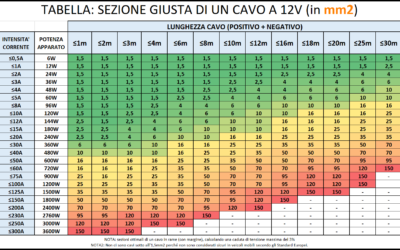
How to Calculate the Right Section of 12V Cables | EASY GUIDE
An undersized cable does not carry enough current. A cable that is too undersized can lead to a fire. An oversized cable, on the other hand, simply costs more and is a waste of money. Are you wondering what is the logicfor choosing one section of cable over...
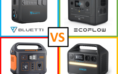
Bluetti vs Ecoflow | Which is the Best Portable Power Station for RV/Vanlife?
The Portable Power Station is an increasingly used accessory on camper vans and RVs, but when does it really make sense to purchase and own or install one? In this article we try to shed some light on how these systems work, the best options on the market, and the...

Van Conversion DIY: How Much Does It Costs? | My Experience
How much does it cost an entirely DIY van to campervan conversion? The queen of all questions... In this article, I want to show you all the costs of my conversion from start to finish, so that you too can get an idea of what it might cost! ...
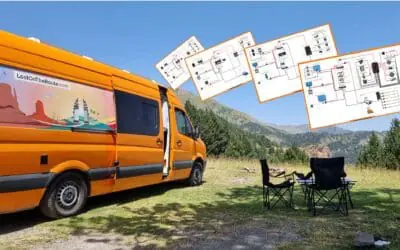
Van Electrical Diagrams for your DIY Project – Ready to Install
The Electrical System is often one of the most complicated steps in a DIY van conversion. How much energy is needed? What apparatus/devices to purchase? How to connect them? How much would it cost? These are all doubts and questions that normally everyone finds...

Van Interior Conversion: Best DIY Ideas for your Project!
The Interior Outfitting of a DIY converted van is both an aesthetic and structural choice. In this article, you will find useful information and inspiration ideas for customizing the Walls, the Ceiling, and the Floor of your Van! DIY CAMPERVAN SET-UP:...

Kitchen for Camper | Best DIY Ideas for your Van Conversion
Cooking in Camper is one of those things, that makes you feel at home wherever you are! Gas, Diesel or Electric Stove? What equipment and accessories you need on the Road? How much space do you need? How to assemble the kitchen in your Camper? In this article you will...

The Best Fridge for Your Campervan – Which One to Choose?
Buying a trivalent or compressor RV refrigerator? Horizontal or vertical? 12V or 110/220V? In this article you will find all the information you need to choose the best fridge for Your Van, tailored to your Needs! 🙂 THE REFRIGERATOR IN THE VAN:...

Van Conversion: How to Build a DIY Bed for your Camper Van
A Camper is not a Camper if it does not have a bed. Where to Sleep and... Dream! In this Guide you can find the inspiration you need for creating a DIY Bed in Your Campervan, And I'll show you step by step how I built a Complete Bed/Dinette on my VW Crafter....
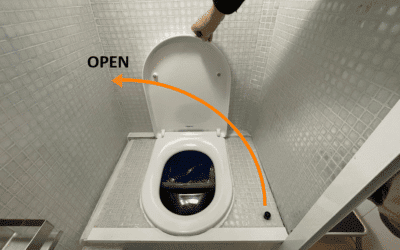
DIY Camper Bathroom: How to Self-Build a Toilet
If you are Campering a Van you surely must have wondered: How does the Bathroom in a Motorhome work? In this Guide I show you the various types of Bathrooms on the market, I explain how they work, and I show you how you can Build yourself an entirely...
Best 12V Fan for RV | DIY Installation Guide | Van Conversion
A Roof Fan helps keep your Vehicle's humidity under control and change stale air. In this guide you will find everything you need to know about mounting a Maxxfan Deluxe fan on the roof of YOUR van. ROOF FAN: WHAT IS IT FOR? Keeping an RV's...
How to Build a Shower in a Do-It-Yourself Camper
A Shower in the RV for some people is not necessary, for others it is a real necessity to be totally independent! In this guide I'll tell you how I built the shower of my converted van entirely Do-It-Yourself! INSTALLING A SHOWER IN A...
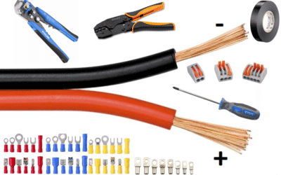
Converting a Van: How to Connect Electric Cables Without Mistaking
Want to know how to "connect" the electric cables in practice in a converted van? Stripping, Crimping, Wire Leads, Clamps, Tubing, Cable Ties and much more... You've come to the right place to learn All That! How to wire your van's electrical...

Converting a Van: All the Camper Products I’ve Used and Where to Buy Them
Where to look for useful tools, accessories and products for campervans? Is it better to rely on local stores or online? In this article, I'll share my experience and show you what I used for my project. 80% OF THE TIME IT TAKES TO CONVERT A VAN,...
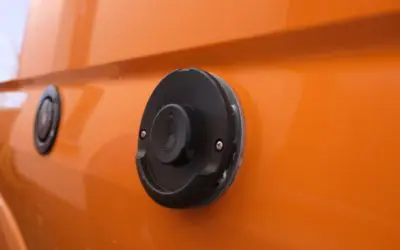
Heating for a Do-It-Yourself Camper: Gas, Diesel or Electric?
No one likes to be cold at home, not even if this is on Wheels! In this article, I'll show you all the possibilities to warm up your Van / RV and enjoy the warmth even on the coldest winter days. HOW TO HEAT UP A DIY CAMPER VAN Winter is definitely not...

Van Insulation: Complete DIY Guide for Beginners
A cosa serve l'isolamento in un Furgone Camperizzato? Come funziona la trasmissione di calore? Quali materiali si possono usare per coibentare il tuo Camper e quali sono i loro vantaggi e svantaggi? In questa Guida, troverai tutte le risposte a queste domande, ed a...
Ultimate DIY Water System Guide for Van Conversion
How much water do you need in your motorhome? Which Tanks to Choose? How to install them? Pipes, Pump, Joints... Find out everything you need to know about creating your RV's water system! VAN CONVERSION: THE WATER/HYDRAULIC SYSTEM Installing a water...

How To Homologate a camper van in Italy – The Complete Guide
If you're entertaining the idea of building a do-it-yourself van to turn it into a Camper, this page is for you! Is it possible to homologate a do-it-yourself motorhome in Italy in 2021? Short Answer: Ni. It is possible yes, but not easy. When I first...

Convert a Van: 10 Things to Know Before You Start
Converting a Van for many is a dream. It's freedom, it's creativity, it's life. Let's not forget though, that converting a van Is also no joke at all. 10 things to know before starting a van conversion When I threw myself, a bit crazily, into the project of...

Van Conversion: How to Install your Windows DIY
Do you have a Van you'd like to convert but it doesn't have the windows you'd like? In this guide, you'll find everything you need to know about installing totally DIY windows for your future RV! Do-It-Yourself Windows: Where to Start? One of the first...

DIY Van Conversion: How to Choose the Best Van for You
Choosing a van is like choosing a Companion of Adventure: it has to be the right one! Which van do I want to convert? This is the first question that will come to your mind if you are thinking of embarking on a Do-It-Yourself conversion. Then again, choosing a...

The Best Vans for DIY Conversion
WHAT ARE THE BEST VANS FOR A DO-IT-YOURSELF CONVERSION? When you're first approaching the idea of converting a van into a camper, the model choice can be a headache. How tall is this one? How long is that? Total length or just of the cargo area? What is the difference...


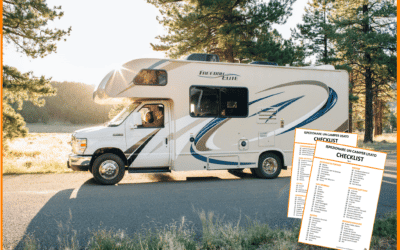


Best and most detailed expiation I’ve come across. The only thing not covered is how to plug into the grid and use power directly with out going via battery and inverter and how to overcome the obvious never ending loop that may be created.
Ciao Dani,
Volevo chiederti: se la batteria (300Ah) ha la possibilità di connettersi col bluetooth, e sia il dc-dc che il regolatore solare sono Victron con bluetooth, serve mettere uno shunt?
Ciao Sandro! Le batterie che ho installato non sono Bluetooth. Due anni dopo, adesso la maggior parte delle batterie di qualità vengono vendute già con bluetooth integrato 🙂
Lo shunt da informazioni che regolatore di carica e DC-DC non danno, come per esempio lo stato di carica delle batterie (percentuale), energia cumulata che entra ed esce. Il regolatore o il DC-DC danno il voltaggio della batteria servizi, ma è un dato “falso”, in quanto influenzato dal fatto che stanno caricando, e che scende di colpo non appena l’impianto di ricarica si spegne.
Se le tue batterie hanno già una app per monitorarne la percentuale di carica, penso che lo smarthshunt si possa skippare, se invece non hai maniera di monitorare la percentuale, allora probabilmente te ne servirà uno.
Hi Dani,
Thank you so much for this very detailed and clear guide, you have no idea how much I appreciate this! It is helping me a ton with planning my electrical system in my camper van.
I do have two question thought that I could not find an answer to here.
1) How did you calculate the cable section and fuse that is between the leisure battery and bus bars?
2) How did you calculate the cable section and fuse that is between the bus bars and 12V fuse box?
Cheers,
Eitan
Hello Eitan!
Actually I wrote a specific topic on wire sizing, but at the moment I haven’t translated it in English (by clicking translate on Google Chrome you can see it in English!).
If you open it though, there’s a complete table that I believe you will understand that might help you in sizing all the wires 🙂
https://lostontheroute.com/it/cavi-12v-volt-calcolo-sezione/
I will translate it next week for giving all info in English too 🙂 Let me know if that is of any help 🙂